
The Traffic Accident Reconstruction Origin -Article-

|
The Traffic Accident Reconstruction Origin -Article-
|
|
Introduction:
Imagine you are standing on a tennis court smashing tennis balls
as hard as you can into a wall. Just a few feet in front of the wall
is a net. You strike a tennis ball as hard as you can. It
crushes into the wall and then bounces back to you. You drive
the tennis ball again, but this time it goes into the net and
slows until it loses all its forward velocity. The net cords
stretched out and arrested the speed of the tennis ball.
The time the tennis ball was interacting with the net was much
longer than the time it took to bounce off the wall.
In a severe collision, the occupant is like the tennis ball. The
occupant can either strike the dashboard, which is analogous to
the tennis ball hitting the wall, or strike the seat belt which is
like the tennis ball hitting the net. How much trauma the body
of the occupant experiences will depend on the time period
over which the force is applied and the stiffness of the body parts
absorbing the force. Is it going to be applied
quickly, or a longer period of time? To reduce the peak force,
the occupant needs the force to be applied over a longest period of time possible.
Stretching the time epoch of the collision for the
occupants and redistributing the crash forces to the stiffest
parts of the human anatomy is the duty of the seat belt. Equally
important, seat belts are the best way to prevent ejection from
the vehicle.
Brief History of Seat Belts:
1903 A patent for a sophisticated system of seat belts and upper torso restraint integrated
into a seat back was obtained by a French automobile manufacturer.
1910 A seat strap was introduced to airplanes, mainly to keep the pilot strapped to
the plane in cases of inverted flying.
1949 Production installed seat belts are offered as an option.
1966 Congress required lap belts (pelvic restraints) for front seat outboard and rear seat outboard
positions.
1967 Congress adopted Federal Motor Vehicle Safety Standards (FMVSS) 208, 209, and 210 dealing with
restraint systems.
1968 Congress requires lap/shoulder belt combinations for all vehicles sold.
1971 FMVSS 208 was amended to specify occupant crash protection and establish a criterion for occupant
crash injury.
1972 Seat belts became mandatory.
1973 The shoulder belt becomes permanently attached to the lap belt.
1974 Ignition interlock systems were required that would not allow the vehicle to be started
unless the seat belt was in use. Requirement rescinded one year later.
1977 Airbags are to be phased in by car size.
1981 Airbag requirement is rescinded.
1987 The passive restraint systems are required with a phase-in.
1993 Mandatory phase-in of dual airbags.
Seat Belt System:
The seat belt restraint system contains some or all of these
components;
1 - shoulder guide loop,
2 - webbing,
3 - non-locking retractor,
3a - retractors (generally),
4 - automatic locking retractor,
5 - emergency locking retractor,
6 - vehicle sensitive retractors,
7 - webbing sensitive retractors,
8 - three point belts,
9 - upper torso webbing,
10 - pelvic webbing,
11 - buckle,
12 - buckle release,
13 - tongue (latch plate),
14 - selvage,
15 - anchorages,
16 - mouse (carrier and track),
17 - adjustment hardware.
Components and Usage:
 (1) The shoulder guide loop, often spoken of as the "d" ring, is
the oval guide that the webbing travels through between the
retractor and the buckle. Typically attached to the 'B' pillar,
or roof line, the shoulder guide loop is often made of metal with
a plastic coating, or completely of a plastic. During collisions
with speed changes greater than about 12 mph, the rapid pay out
of webbing sliding through this ring can burn and abrade the
nylon covering and leave telltale marks of usage of the belt.
(1) The shoulder guide loop, often spoken of as the "d" ring, is
the oval guide that the webbing travels through between the
retractor and the buckle. Typically attached to the 'B' pillar,
or roof line, the shoulder guide loop is often made of metal with
a plastic coating, or completely of a plastic. During collisions
with speed changes greater than about 12 mph, the rapid pay out
of webbing sliding through this ring can burn and abrade the
nylon covering and leave telltale marks of usage of the belt.
 (2) The webbing is a narrow fabric woven with continuous filling
yarn and finished with selvages. During a significant collision,
great enough frictional forces can be generated to melt nylon
material from the d-ring onto the webbing, skin can also be
abraded or melted onto the webbing.
(2) The webbing is a narrow fabric woven with continuous filling
yarn and finished with selvages. During a significant collision,
great enough frictional forces can be generated to melt nylon
material from the d-ring onto the webbing, skin can also be
abraded or melted onto the webbing.
The belt (now typically a polyester weave with less elastic
property but higher tensile loading capabilities) length and a
coating of foreign materials like dirt or blood can also be
indications of usage. The federal law mandates the width of the
webbing to be not less than 1.8 inches except those portions that
do not come into contact with the 95 percentile test dummy.
(3) The non-locking retractor allows the webbing to be spooled
out at any time without locking and stopping this from happening.
This is an older form of the retractor
(the original form) and
the occupant was responsible for adjusting the webbing length
once the belt was buckled. The retractor would spool in excess
webbing for stowage inside the retractor housing.
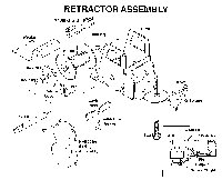
(3a) The retractor itself consists of various components (see illustration to
left). The primary parts are the
frame, which houses
the mechanism; the spool, which winds the webbing up; the ratchet
is located on the sides of the spool and are a portion of the
mechanism to stop the spool-out; the spring assembly which acts
to put tension on the spool to allow it to draw up the webbing;
the lock pawl (A4) is a bar that is forced into position across
the teeth of the ratchets; the G-sensor is an inertial device
that when free to move, releases or applies a force to a spring
which moves the lock pawl or allows the lock pawl to move into
position across the ratchets. For comfort, to maintain a certain
length, a ratchet lever will engage with the teeth of the
ratchet.
Also, in webbing sensitive mechanisms, pins on the side of the
ratchet stick out. Inertial bars, attached to light springs and
mounted to the outer sides of the spool hub, spin freely under
normal rotations. Under rapid rotation, with a sudden spool out
the inertia of the bars pull them outward elongating the spring
and causing the bars to quickly engage with the pins and lock the
retractor. Some design have multiple retractors, often in door
mounted passive/active systems.
(4) The automatic locking retractor allows the webbing to be with
drawn and then rewound but will not permit a second withdrawal
until the belt is nearly completely rewound. This device allowed
for the installation of a locking device within the mechanism
located inside the retractor housing. The mechanism was
typically a clutch and locking bar combination which would engage
if the belt spooled up an amount when it was in use.
(5) The emergency locking retractor allows the belt to spool out
and rewind freely except when a vehicle acceleration demands it
locks up. The mechanism may be of an inertial reel nature or
vehicle sensitive type.
(6) The vehicle sensitive retractors act similar to the emergency
locking retractors when the vehicle tilts at greater than a 15-degree pitch (0.26 G) or decelerates at greater than or equal to
0.7 G in ANY direction. This system allows for less spool out of
the webbing.
The mechanism for the lock up is a pendulum or other inertial
device which resists the acceleration of impact and causes a
bar to lock across the ratchets of the retractor. The
pendulum hangs freely and moves slightly in relation to the frame with changes in
acceleration. An accelerations of more than 0.7 G is great enough to
overcome the inertial force and swing the pendulum fully which,
in turn activates the locking bar or pawl which stops the motion
of the teeth of the retractor ending spool out. Another form of
the inertial device is a steel ball which moves under a
sufficiently large acceleration and causes the engagement of the
lock pawl or a clutch which stops the spool out.
The distance of travel between the pawl and the teeth are less
than or equal to 1/10 of one inch. The lock up force is along
the order of 0.3 G to 0.5 G, and occurs in about 15 ms to 30 ms
(0.015 - 0.030 seconds), but may be as rapid as 9 ms. At the
first lock up the reel will engage and halt the pay out of
webbing and then, with rebound into the seat the spring tension
on the reel will wind up any additional slack created.
Older models of the pendulum were free to drop through a hole in
the roof of the G-sensor housing if the vehicle over turned and
thus, releases the ratchet allowing free spool out of the
webbing. Newer devices have a ring which denies the pendulum
from dropping through the top plate of the G-sensor housing
should the vehicle overturn and prevents the pawl from
disengaging.
(7) Webbing sensitive retractors automatically lock when the
webbing is suddenly withdrawn, they do NOT lock when the webbing
is slowly spooled out. The mechanism of lock up was a mass
attached to a light spring. When the retractor began to rapidly
spin with sudden pay-out, the mass would lock up the spool and
prevent further withdrawal of the webbing from the spool hub.
 (8) Three point restraints are seen in many vehicles today, the
pelvic webbing and torso webbing are sewn together at the buckle
area to maintain one triangular shaped belt. One end may be
fixed to the vehicle near the door sill without a retractor or
both pelvic and torso webbing may operate with separate
retractors (often seen in the door mounted systems).
(8) Three point restraints are seen in many vehicles today, the
pelvic webbing and torso webbing are sewn together at the buckle
area to maintain one triangular shaped belt. One end may be
fixed to the vehicle near the door sill without a retractor or
both pelvic and torso webbing may operate with separate
retractors (often seen in the door mounted systems).
A continuous loop belt is a one retractor system. Typically, a
floor anchor is used for the buckle and one portion (the distal
end of the pelvic webbing)of the loop. The torso webbing feeds
up from the retractor through a guide loop typically mounted on
the 'B' pillar and the latch plate slides on the webbing via a
guide loop. Movement of the latch plate may be limited by a
button or build up of material sewn onto the webbing.
(9) The upper torso webbing (shoulder belt or shoulder strap) may
be a part of a continuous belt or may be separately attached to a
motorized mouse that runs along a track. The upper torso belt
typically spools from a retractor and locks into a buckle with/or
as part of a separate system with the lap belt.

(10) The pelvic webbing or lap belt may be part of a continuous
system or may be separate in the case of some active/passive
design systems. It runs from a retractor to a buckle that it
latches into, often in conjunction with the torso webbing.
(11) The buckle is the one piece housing that surrounds the
release and may extend up from the floor mounted anchorage. The
system is functioning or "buckled" when the latch plate has
clicked home into the receiving portion of the buckle.
(12) The release is the button in the portion of the buckle
housing that allows the tongue to disengage from the buckle
receiver. The release is designed to minimize unintended
activity and should not release with a force less than or equal
to 30 pounds.
Releases may be on an end or located near the center of the
buckle.
(13) The tongue is the metal plate that is surrounded by, but
extends from the conjunction of the webbing or may slide somewhat
freely on the continuous loop webbing. Typically the tongue
(latch plate) has a slot in it for engaging with the receiving
end of the buckle mechanism. The latch plate often has its own
guide loop which may be constructed from metal or plastic.
(14) The selvages are the woven edges of the webbing.
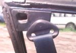
(15) Anchorages are technically defined as "attachment hardware"
and must be manufactured to meet certain loading requirements.
 (16) Mouse. (Carrier and track assembly). The mouse is a small
motorized unit that attaches the distal end of the upper torso
restraint for those types of passive systems that use this
mechanism. When the door is opened, the mouse runs forward on a
track along the head liner or sill and when the door is closed,
the mouse runs rearward positioning the torso belt in place. The
upper torso restraint is sometimes anchored to the floor with its
own buckle. A buckle and emergency release is designed into the
mouse in that device. Some systems employ separate buckles for
the upper torso (passive) and the pelvic (active) webbing.
(16) Mouse. (Carrier and track assembly). The mouse is a small
motorized unit that attaches the distal end of the upper torso
restraint for those types of passive systems that use this
mechanism. When the door is opened, the mouse runs forward on a
track along the head liner or sill and when the door is closed,
the mouse runs rearward positioning the torso belt in place. The
upper torso restraint is sometimes anchored to the floor with its
own buckle. A buckle and emergency release is designed into the
mouse in that device. Some systems employ separate buckles for
the upper torso (passive) and the pelvic (active) webbing.
(17) Adjustment hardware. This type of hardware is designed to
fit the belts to the individual user and includes the buckle,
attachment hardware and the retractor.
Load Limiters:
 Load limiters are simple mechanisms to increase the ride-down
time of the event for the occupant while staying below the limits
of torso over load. Systems manage the energy by deforming at
the anchorage or the use of a metal honeycomb covering that
deforms prior to the onset of extreme tensile loading on the
webbing.
Load limiters are simple mechanisms to increase the ride-down
time of the event for the occupant while staying below the limits
of torso over load. Systems manage the energy by deforming at
the anchorage or the use of a metal honeycomb covering that
deforms prior to the onset of extreme tensile loading on the
webbing.
Energy management loops are a series of webbing folds, located
near the anchorage, sewn together accordion fashion. As the
tensile loading on the webbing approaches a limit (typically less
than 1,500 lbf - which has been shown may cause serious chest
injuries) the stitches break releasing some of the folds and
absorbing additional kinetic energy through the webbing.
Slack:
Most manufacturers report that having in excess of 1.5 inches of
slack in the belt will create excessive webbing and will allow
for too great a payout of the belt, increasing the travel
distance (excursion) of the occupant.
Pre-tensioners:
Excessive slack may be accumulated due to bulky clothing or
manipulation of the webbing for comfort. The purpose of the pre-tensioner is to take up excess webbing that has spooled out
immediately before the collision forces act on the occupant (15
ms - 30 ms). This allows for a tighter couple between the
car/restraint and occupant system and reduces the length of the
travel for the occupant with a better apportioning of the
collision forces.
One system also works with a cable and pulley system affixed to
the engine that tugs the cable and tightens the webbing as the
engine of the car is moved rearward, or more commonly it may
operate on a sensor and explosive charge that fires a short bolt
that takes the slack out of the webbing.
Inertial devices also are employed as pre-tensioners and
grabbers. Grabbers grip the webbing and stop the spool out of
webbing slack that is not tightly spooled around the hub.
Typically, pre-tensioners and grabbers work in the 12-mph delta v
range and may remove as much as six inches of slack from the
system. The pre-tensioner typically operates in the range of 17
ms (0.017 seconds) and may activate prior to the airbag beginning
to deploy.
Explosive pre-tensioners DO NOT WORK if the seat belt is not
buckled.
Types of seat belts:
Type 1: A lap belt only for pelvic restraint.
Type 2: Is a combination of pelvic and upper torso restraint.
Type 2A: A separate shoulder belt intended to be used in conjunction with a lap belt to form a type 2 assembly.
Passive restraints: The type of restraint that requires NO action
on the part of the occupant to put the device in place. Passive
restraints were designed to increase the lack of compliance with
seat belt usage.
Active restraint: The occupant is required to take some action to
ensure the restraint is worn.
Passive/Active: There are combinations that have a passive torso
restraint and an active pelvic restraint.
Pay-Out or Spool Out:
This is the webbing length that is created by the loosely wrapped
webbing around the spool hub having the slack removed, as well as
the amount that is pulled from the retractor prior to its
locking.
FMVSS 208 - Occupant Crash Protection:
Passenger cars manufactured since 1972 have been required to meet
specifications for crash protection at certain locations in the
car. The manufacturer could comply with these demands in three
ways:
(1) First Option: - Complete Passive Protection. The vehicle shall meet crash protection requirements
as set forth by means that require no action by vehicle occupants (passive restraints).
(2) Second Option: -Lap Belt Protection System With Belt Warning. Have a type 1 or type 2 belt (with a
detachable shoulder portion) at designated seating positions with a warning (audible or visible to driver)
device.
(3) Third option: - Lap and Shoulder Belt Protection With Belt Warning. Standards similar to the
second option.
More recently the standard has shifted to primarily passive
systems.
Crash protection:
The standards set forth these criteria: The vehicle, at any speed
up to and including 30 mph, is crashed into a fixed barrier that
is perpendicular to the line of travel of the vehicle, or at any
angle up to 30o; the instrumented test dummy must not show
accelerations, or loading of specific areas, higher than set
forth in FMVSS 209; no part of the system may fail.
Side Impact:
A barrier weighing 4,000 lbs. with a vertical, rigid, flat,
rectangular surface, 6.5 feet wide by 5.0 feet high, is
accelerated in a straight line and crashed into the side of the
car. The barrier cannot undergo any significant static or dynamic
deformation and absorb no significant portion of the energy
resulting from the impact, save rebound velocity.
Injury Criteria:
( A ) The anthropometric test dummies shall be completely
contained during the test.
( B ) The dummy shall not record a resultant head acceleration
such that the equation:

shall exceed 1,000, where a is the resultant acceleration
expressed as a multiple of the acceleration of gravity (g) and t1
and t2 are any two points in time during the crash of the vehicle
which are separated by not more than a 36-ms time interval (0.036
seconds).
( C ) The resultant acceleration of the c.g. of the upper thorax
shall not exceed 60 G's, except for intervals whose cumulative
duration is not more than 3 ms.
( D ) The compressive force transmitted axially through each
upper leg shall not exceed 2,250 lbs.
FMVSS 209 - Seat belt assembly requirements:
Webbing breaking strength:
6,000 lbf Type 1
5,000 lbf Type 2, 2a - pelvic*
4,000 lbf Type 2, 2a - shoulder*
(* together)
Elongation percentage belt type load
20% Type 1 2500 lbf
30% Type 2 2500 lbf - pelvic
40% Type 2 2500 lbf - torso
Emergency Locking Retractor:
Shall lock before webbing extends one inch when the retractor is
subject to a deceleration 0.7 G. Shall NOT lock before the
webbing extends more than two inches when the retractor is
subject to a deceleration of 0.3 G.
Attachment hardware:
Anchorages and all hardware must be able to withstand the same
loading as the webbing. The performance of the system shall not
fail at 20 G. The hardware must withstand a force of 9,000
lbs. except that in which the ends of two or more assemblies
cannot be attached to the vehicle by a single bolt shall have a
breaking strength of not less than 5,000 lb. Hardware designed
to receive the ends of the two seat belt assemblies shall
withstand a tensile force of at least 6,000 lbs.
Buckle Release:
The buckle of a type 1 or type 2 seat belt shall release when a
force of not more than 30 lbs. is applied.
Buckle:
The buckle of a type 1 or type 2 seat belt assembly shall NOT
release under a compressive force of 400 lbs. Metal to metal
buckles when in PARTIAL engagement shall separate by a force of
not more than 5 lbs.
Structural Components:
Type 1: The assembly loop shall withstand a force of not less
than 5,000 lbs., and each component shall withstand a force of
not less than 2,500 lbs. The loop shall not extend more than 7
inches when a force of 5,000 lbs. is applied. The length of the
assembly between anchorages shall not increase more than 14
inches under a force of 5,000 lbs. Any webbing cut by hardware
shall have a breaking strength at the cut of not less than 4,200
lbs. Complete fracture of any solid section of metal attachment
shall not occur during the test.
Type 2: The structural components of the pelvic restraint shall
withstand a force of not less than 2,500 lbs. The structural
components of the upper torso restraint shall withstand a force
of not less than 1,500 lbs. The structural components of the
assembly that are common to the pelvic and the upper torso shall
withstand a force of not less than 3,000 lbs. The length of the
pelvic restraint between anchorages shall not increase more than
20 inches when subjected to a force of 2,500 lbs.
The length of the upper torso restraint between anchorages shall not increase more than 20 inches when subjected to a force of 1,500 lbs. Any webbing cut by hardware during the test shall have a breaking strength of not less than 3,500 lbs. for the pelvic webbing and not less than 2,800 lbs. for the upper torso webbing. No complete fracture through any solid section of metal attachment hardware is allowed.
FMVSS 210:
Seat belt anchorages, attachments, hardware and attachment bolts
must withstand a 5,000 lb. force. Type 1 and type 2 seat belt
anchorages must withstand a 5,000 lbf load for 10 seconds. The
load is applied at an onset rate of not more than 50,000 pounds
per second, and attaining the 5,000 lbf load in not more than 30
seconds. Type 2 (automatic) seat belt anchorages must withstand
a 3,000 lbs. for 10 seconds when that load is applied with an
onset rate of not more than 30,000 lb/second, and attaining the
3,000 lbf load in not more than 30 seconds. The load for each
test must be applied in the direction in which the seat faces to
a pelvic block, at an angle of not less than 5 degrees or more
than 15 degrees.
Mandatory Usage Laws:
Mandatory use laws immediately increased compliance in many areas
by about 15% of the driving population, but passive restraints
alone tend to receive nearly 80% compliance.
Primary Direction of Force:
The PDOF is a physical property imparted to an object during the
impulse as a result of being involved in a collision. The normal
and tangential forces at a contact area combine to yield a single
resultant force at their peak or limit, often spoken of as
maximum engagement. This force, imparted by a component of the
momentum change of each car (which is relative to the mass of the
effected vehicle) can be thought of as acting in a single
direction. The occupants will "appear" to move opposite of the
PDOF when, in reality, the vehicle is suddenly accelerated in the
direction of the PDOF and the inertia of the occupants causes the
car to move toward them.
Delta v:
By definition:

Delta v, means generally a change of velocity, the term has a
specific meaning in the accident reconstruction community. It is
identified as the instantaneous change in speed that occurs
during the momentum exchange at Impulse (F dt).
As the definition of acceleration (above) indicates, the instantaneous change in the magnitude and direction of the velocity is equivalent to the instantaneous change in the magnitude and direction of the acceleration during the time period of the momentum exchange. This change in velocity has been shown to be a good indicator of the level of injury an occupant may receive.
Conclusion
This introductory paper has covered basic seat belt nomenclature. Types of seat belt systems and how they function were also presented. Finally some basic theory was discussed. In the next installment a general method for examining and testing restraint systems will be developed.
Sources:
SAE TOPTECH - Passive Restraints
SAE 840396 - Diagnosis of Seat Belt Usage in Accidents.
SAE 840392 - Historical Perspective on Seat Belt Restraint Systems
NHTSA - FMVSS 208, 209, 210
Texas A & M - Biomechanics Course
Biomechanics of Trauma, by Nahum and Melvin
CHP Academy - lecture notes from TAR
The position provides on-scene documentation through total station survey and photography of traffic collisions involving severe injuries and death. The entire County population is over 3 million residents, and the County maintains over 1,800 miles of roadways. Mr. Phillips has investigated hundreds of fatal collisions during his time with the County. He is used as a consultant for allied agencies, County Counsel and the District Attorneys' Office.
Mr. Phillips has consulted with Law Firms through out the western United States as well as the State Attorney Generals Office and the Department of Transportation.
Mr. Phillips holds Bachelor Degrees in Criminal Justice and Engineering (Manufacturing) and has attended many hundreds of hours of specific technical training in the field of collision reconstruction.
He can be contacted at [email protected]
|
Copyright ©
|